
As I wrote in my previous post, for these days i’ve been working in a simple project with my friends. Actually it’s just a simple project, controlling an rgb lamp/led using android via bluetooth. The idea comes from this kickstarter project and i think it’s very feasible and likely easy, at least to make the prototype or demo. After around 4 days searching (component) and working, eventually i made the simple demo. My Xperia successfully controlled 3 pieces RGB led, driven by ATMega16’s pwm (pulse width modulation), and serial communication was done via bluetooth. I’ll make the complete tutorial, but for now i’ll just show you the basic : how the communication is established. First, look at video I captured below.
In this demo, i use my own AVR development board (ATMega16 chip) whose header for standard 16×2 LCD at PORTc. You can see the one blinking blue, that is HC-05 bluetooth module. I bought it from local store ANNAM electronics (www.anam-mahal.com) for IDR 145000 and i use my mobile phone Sony Xperia L running on android 4.2.2 as the bluetooth host. Interested? just follow tutorial below 🙂

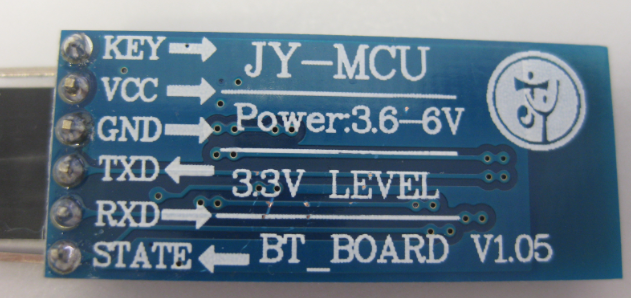
Bluetooth Module HC-05 with MCU board (level converter)
1. Microcontroller Basic
First thing first, you have to know how serial communication in atmega works because HC-05 bluetooth is a serial module. So basically, atmega16 utilize USART to establish a communication. It’s very simple because we just need two pins of ATMega16, Rx (receive) and Tx (transmit) at PORT0 and 1, respectively. Let’s say you want to make communication between PC and AVR. All you need is just connect Rx of PC to Tx of AVR, and vice versa.
Then consider your android as PC above, and you want to make wireless communication. Bluetooth module is put in the middle to send-receive data wirelessly. A problem that would be an issue is, i think, just the baud rate. You must set the same baud rate for AVR and bluetooth. It’s a bit confusing for atmega because we must understand the register. But don’t worry, CVAVR’s wizard will help you!
2. HC-05 Bluetooth
HC-05 is a bluetooth serial module, used for converting serial port to bluetooth. HC-05 has two modes of operation : master and slave, but for now you just need it as a slave. If you prefer the cheaper module, you can pick HC-06 instead. The function of HC-06 and HC-05 are mutually compatible with each other. HC-06 is a former version that user can’t change the mode. But it’s ok since we only working with slave mode for bluetooth module.
To make this module run, you just need to connect 4 pins : vcc,gnd,rx,tx. But note that HC-05, as well as HC-06 works with 3.3 V voltage so you must convert this level into ATMega’s working voltage : 5 V. You can buy separately JY-MCU board for HC-05 or sometimes it comes with a board so you don’t need to add level converter (i recommend this one). Here is a useful page to visit.
The Board
3. Set Up Connection
To set up the connection/wiring, look at this illustration.

Illustration of the system
Be sure you’ve converted the logical level of Bluetooth module to ATMega’s working voltage (5V). Be careful of Vcc needed to power this module. Check the datasheet provided by manufacturer to ensure, because once the module wrongly powered (too high voltage), your project is ruined and waste of IDR 145000.
4. Program the chip – registers
Use CodeVision AVR C compiler to compile and build the hex file, because it will help you out of specifying register. But don’t worry i’ll describe the register so you understand the baud rate. Before setting the register, look at HC-05 specification. It says that : “Slave default Baud Rate : 9600, Data bits:8, Stop bit:1, Parity:No parity”. To satisfy these needs, configure :
USART Control and Status Register C – UCSRC

Leave URSEL and UCPOL as its default value. UMSEL = 0 for Asynchronous Operation. UPM is used to define type of parity, choose UPM1:0 = 00 to disable because we need no parity. UCSZ2:0 = 011 because character size is 8 bit for serial communication (But UCSZ2 is in another register). So we have value 0x86 or 0b10000110 for UCSRC. Please look at ATMega16 datasheet for details.
USART Control and Status Register B – UCSRB

We don’t use interrupt, so leave RXCIE and TXCIE 0. Leave UDRIE too, because it is a flag that indicate whether UDR is empty. Set RXEN because we want ATMega to receive data, and just let TXEN 0 because now we want to set up just one way communication. Finally value for UCSRB = 0x10 or 0b00010000.
USART Baud Rate Registers – UBRR

Follow first row for async mode. Since the default baud rate for HC-05 is 9600, then UBRR = f/(16×9600) – 1 . In my project, i use ATMega internal oscilator 8Mhz. So i’ll need UBRR = 51 or 0x33.
Last, set PORTC as output since we equip LCD at PORTC. DDRC = 0xFF
5. Program the chip – coding
First, include the corresponding library and initialization of LCD module
#include <mega16.h>
#include <stdio.h>

// Alphanumeric LCD Module functions
#asm
   .equ __lcd_port=0x15 ;PORTC
#endasm
#include <lcd.h>
Ah, don’t forget to set your system clock frequency when configure the wizard. If you forget, you can set manually by selecting Project -> configure and then click compiler tab.

And then declare any global variable and set the register as i told you before.
void main(void)
{
// Declare your local variables here

unsigned int i;
char data;
char buffer[10];

PORTC=0x00;
DDRC=0xFF;

PORTD=0xFF;
DDRD=0x00;
// USART initialization
// Communication Parameters: 8 Data, 1 Stop, No Parity
// USART Receiver: On
// USART Transmitter: Off
// USART Mode: Asynchronous
// USART Baud Rate: 9600
UCSRA=0x00;
UCSRB=0x10;
UCSRC=0x86;
UBRRH=0x00;
UBRRL=0x33;

ACSR=0x80;
SFIOR=0x00;

lcd_init(16);

i=0;

while (1)
{
// Place your code here
}
Set PORTC as output. And then to set PORTD as input by typing DDRD = 0 (we just use pin Rx to receive, so ignore Tx). A step you must consider is writing logic one for input pin to activate pull up resistors. Pull up resistors will avoid pin having tri stated inputs. In input mode, when pull-up is enabled, default state of pin becomes ‘1’. So even if you don’t connect anything to pin and if you try to read it, it will read as 1. Now, when you externally drive that pin to zero(i.e. connect to ground / or pull-down), only then it will be read as 0.
However, if you configure pin as tri state. Then pin goes into state of high impedance. We can say, it is now simply connected to input of some OpAmp inside the uC and no other circuit is driving it from uC. In this case, if pin is left floating (i.e. kept unconnected) then even small static charge present on surrounding objects can change logic state of pin. If you try to read corresponding bit in pin register, its state cannot be predicted. This may cause your program to go haywire, because our program depends on input from particular pin, that is Rx. See datasheet page 52 for detailed information.
Main Program
So, you have understood about USART and uC. Now let’s begin the main section of the program. Take a look at this flowchart before go further

Waint until data is received can be implemented by checking the bit RXC at UCSRA. RXC is a flag that will be set when a data has been completely transmitted to Rx pin, and it’s not been read. This data is stored at register UDR, and to read that, simply assign a char with UDR. Then check data whether it is ‘#’ or not, because ‘#’ is used to terminate string. (i’ll explain later in android section). If data coming is not ‘#’, add it to a string buffer and wait for the next character. Else if data coming is ‘#’, it means that android has completed the transmit of one string and terminate string buffer. Finally, show the string to LCD. You may place below code inside the main loop.
while(!(UCSRA & (1<<RXC)))
{
//do nothing
}
data = UDR;
if (data != '#')
{
buffer[i] = data;
i++;
} else
{
buffer[i]='\0';
i=0;
lcd_clear();
lcd_gotoxy(0,0);
lcd_puts(buffer);
}
Download program
Compile program and fix maybe you find some errors. Download the program to your chip using any downloader you like. I use downloader USBASP programmer and software ProgISP. Don’t forget to set the fuse bit correctly. Because wrong clock will cause different UBRR value and the data will be read differently from what it has to be (different baud rate). I set fuse bit D9 E4 to utilize calibrated internal RC Oscillator. I’ll write some post related to fuse bit because it usually comes to an issue after one wrongly set fuse bit and thee chip is broken.
6. Android Programming
Now come to hardest part : make android application. If you’re an electronic hobbyist and don’t want to have a mess with android, you may download application in play store named “Arduino Bluetooth Terminal”. But if you are not a beginner in android, i’m sure you’ll find this easy. I’ll try to describe as simple as you ‘ll understand. ps : I use eclipse IDE to build android program.
Starting up
Make new project in eclipse. File -> new -> android application project. Fill in the blank for app name, package, etc. Then finish. See AndroidManifest.xml andd add 2 permissions : android.permission.BLUETOOTH and android.permission.BLUETOOTH_ADMIN. Make layout which contains 2 text fields and a button to go to the next page/activity. My layout looks like this


We will need 2 pages/activities so create another activity. File -> new -> other -> Android Activity. Change the activity name to Send.java and layout to activity_send.xml. The layout looks like above. You don’t need to add ListView because it is used to receive incoming data from uC. Android just send data to uC.
MainActivity
Before code the main program, i suggest you to read bluetooth documentation on android developer website. Click this.
So first thing we do is to verify that bluetooth is supported on the device, and ensure that it is enabled. Copy code below under onCreate method
SharedPreferences localSharedPreferences = getSharedPreferences("dataardubtterm", 0);
myBTadapter = BluetoothAdapter.getDefaultAdapter();
		if (this.myBTadapter == null) {
			Toast.makeText(getApplicationContext(),
					"Device doesn't support Bluetooth", Toast.LENGTH_SHORT)
					.show();
		}
		while (this.myBTadapter.isEnabled()) {
			return;
		}
if bluetooth adapter has been enabled, break from onCreate method. But if it’s not, request that bluetooth be enabled, call startActivityForResult() with the ACTION_REQUEST_ENABLE action intent.
startActivityForResult(new Intent(
				"android.bluetooth.adapter.action.REQUEST_ENABLE"),
				this.REQ_BT_ENABLE.intValue());
		Toast.makeText(getApplicationContext(), "Enabling Bluetooth!!",
				Toast.LENGTH_SHORT).show();
And then add method to handle activity result
protected void onActivityResult(int paramInt1, int paramInt2,
			Intent paramIntent) {
		if (paramInt1 == this.REQ_BT_ENABLE.intValue()) {
			if (paramInt2 == -1) {
				Toast.makeText(getApplicationContext(),
						"BlueTooth is now Enabled", Toast.LENGTH_SHORT).show();
			}
			if (paramInt2 == 0) {
				Toast.makeText(
						getApplicationContext(),
						"Error occured while enabling.Leaving the application..",
						Toast.LENGTH_SHORT).show();
				finish();
			}
		}
	}
Last, add code to listen for click button
public void save(View paramView) {
 SharedPreferences.Editor localEditor = getSharedPreferences(
 "dataardubtterm", 0).edit();
 this.edittxtDevName = ((EditText) findViewById(R.id.txtDevname));
 String str1 = this.edittxtDevName.getText().toString();
 this.edittxtuuid = ((EditText) findViewById(R.id.txtbtservice));
 String str2 = this.edittxtuuid.getText().toString();
 localEditor.putString("DevName", str1);
 localEditor.putString("btservice", str2);
 localEditor.commit();
 startActivity(new Intent(this, Send.class));
 }
I forgot. You can use android shared preferences to store data that has been entered to text fields (bluetooth shield name and service UUID). This data will be used again in the send activity. That’s why we declare localSharedPreferences in onCreate method.
Send Activity
Before establish communication, android must find and connect to the bluetooth shield. Again call BluetoothAdapter tofind remote bluetooth devices either through device discovery or by querying the list of paired (bonded) devices. In this case, we have already knew the name of shield we want to connect. So we don’t need to find any other shield, just querying paired devices and connect to desired shield with corresponding name. NOTE : you must pair bluetooth manually in the phone setting (bluetooth module default name = HC-05, pin = 1234) unless you do device discovery to search and requesting some information about each bluetooth enabled device in the local area.
void findBT() {

		// mengecek nama bluetooth slave yang akan dikirim data (sudah diset
		// pada activity sebelumnya)
		strDevname = getSharedPreferences("dataardubtterm", 0).getString(
				"DevName", strDevnamed);

		// mengecek apakah device mendukung bluetooth
		mBluetoothAdapter = BluetoothAdapter.getDefaultAdapter();
		if (mBluetoothAdapter == null) {
			myLabel.setText("No bluetooth adapter available");
		}
		if (!mBluetoothAdapter.isEnabled()) {
			startActivityForResult(new Intent(
					"android.bluetooth.adapter.action.REQUEST_ENABLE"), 0);
		}

		// mencari bluetooth slave yang sudah pair dengan device
		Set<BluetoothDevice> localSet = mBluetoothAdapter.getBondedDevices();
		Iterator localIterator = null;
		if (localSet.size() > 0) {
			localIterator = localSet.iterator();
		}
		for (;;) {

			// kondisi tidak ditemukan paired slave/device
			if (!localIterator.hasNext()) {
				return;
			}
			BluetoothDevice localBluetoothDevice = (BluetoothDevice) localIterator
					.next();

			// jika ditemukan bluetooth slave dengan nama yang sama dengan yang
			// telah diset, maka set itu menjadi device
			if (localBluetoothDevice.getName().equals(strDevname)) {
				mmDevice = localBluetoothDevice;
				myLabel.setText("Bluetooth shield available.");
				btdev = true;
				return;
			}
			myLabel.setText("No bluetooth shield available.");
		}
	}
In the above code, after querying for bonded devices, we check each one of the localSet to find whether there is a paired device of the same name with shield we want to connect. If found, we assign that bluetoothDevice of localSet to our global field BluetoothDevice. And then make one more method that aims to form serial connection between uC and android. Look at this to see complete instruction connecting devices.
void openBT() throws IOException {
		if (this.btdev) {
			this.strbtservice = getSharedPreferences("dataardubtterm", 0)
					.getString("btservice", "1101");
			UUID localUUID = UUID.fromString("0000" + strbtservice
					+ "-0000-1000-8000-00805f9b34fb");
			// UUID diatas digunakan saat device memerintahkan socket mengirim
			// data secara serial (1 bit/waktu)

			mmSocket = mmDevice.createRfcommSocketToServiceRecord(localUUID);
			mmSocket.connect();
			mmOutputStream = mmSocket.getOutputStream();
			mmInputStream = mmSocket.getInputStream();
			// beginListenForData();
			myLabel.setText("Bluetooth shield connected.");
		}
	}
Place method findBT() and openBT() in onStart() method. Actually, these work should take place in separate thread because forming a connection can block a thread for a significant amount of time. Up until now, all of the program’s code has been written in the main thread or UI thread. You will notice later a little lag when switching activity because between these activity, the connection is established. You may curious what is UUID. Here i quotes from android doc
A Universally Unique Identifier (UUID) is a standardized 128-bit format for a string ID used to uniquely identify information. The point of a UUID is that it’s big enough that you can select any random and it won’t clash. In this case, it’s used to uniquely identify your application’s Bluetooth service. To get a UUID to use with your application, you can use one of the many random UUID generators on the web, then initialize a
UUIDwithfromString(String).
UUID for serial communication is 0000-1101-0000-1000-8000-00805f9b34fb
The last, make a method to sendData. This is as easy as getting text from text fields, write to the output stream, and flush the output stream to send data to bluetooth module.
void sendData() throws IOException {
		if (btdev) {
			String str = myTextbox.getText().toString() + '#';
			mmOutputStream.write(str.getBytes());
			mmOutputStream.flush();
			myLabel.setText("Data sent.");
		}
	}
Of course you have to make a clicklistener for button “Send”. The onCreate method become like this
public void onCreate(Bundle paramBundle) {
		super.onCreate(paramBundle);
		setContentView(R.layout.activity_send);
		//ArrayList list = new ArrayList();
		Button sendButton = (Button) findViewById(R.id.send);
		myLabel = ((TextView) findViewById(R.id.label));
		DataBt = ((TextView) findViewById(R.id.label2));
		myTextbox = ((EditText) findViewById(R.id.entry));
		listDevicesFound = ((ListView) findViewById(R.id.receivedata));
		btArrayAdapter = new ArrayAdapter(this,
				android.R.layout.simple_list_item_1);
		listDevicesFound.setAdapter(this.btArrayAdapter);
		sendButton.setOnClickListener(new View.OnClickListener() {
			public void onClick(View paramAnonymousView) {
				try {
					sendData();
					return;
				} catch (IOException localIOException) {
				}
			}
		});
	}
Ah, almost forget. Be sure you close the bluetooth connection when finish the application. Close any stream and socket. Place the code inside method onDestroy() or onStop()
void closeBT() throws IOException {
		if (btdev) {
			stopWorker = true;
			mmOutputStream.close();
			mmInputStream.close();
			mmSocket.close();
			myLabel.setText("Bluetooth closed.");
		}
	}
AAAND VOILA IT’S DONE 🙂

Watch my first video above to look how this app run. HC-05 will differently blink when powered or connected. Slow flicker (1Hz) represents emtering communication mode while fast flicker (2Hz) represents “pairable mode” which it wait to be discovered and connected
with the complete code, program will run correctly. Feel free to ask or request for apk,hex,or project file at comment below 🙂 🙂

Pingback: DIY Home Automation, Berinteraksi Dengan Alat Elektronik | Adhitya Reza·
nice tutorial. Can you tell me how to send current date and time via bluetooth to the avr . Thanks 🙂
there are many ways to achieve that. Android can retrieve current time and date in many different formats.
here i just tell the idea :
1. retrieve data and time (just google that) ,
2. convert to string with format that will be easy to be understand and parsed by AVR. (since programming in AVR is much more limited than in android)
3. send and receive that data via bluetooth, serially of course
maybe i’ll come with tutorial next post next time
Hey wonderful tutorial , can you share the code ? i am actually doing a similar project where i have to glow leds on pressing buttons from android device . i am using PIC16F77A and HC05
Of course. Send email to adhityarz@gmail.com i’ll reply 🙂
How to communicate between two bluetooth using microcontroller? Do we have set the 1’st bluetooth as master and the other as slave?
can u plz mail me the apk at soumyadip.auddy@gmail.com
I really need it for bluetooth to avr communication.
Thanks in advance.
hey man that was nice. I am myself building something like this. Can you please give me the android app you used.
I am having a problem that the data i receive is not correct. lcd just displays a blop at that point. I know that i am receiving something but thats it.
Thanks in advance
Basil, have you sent msg to my email? I’ll reply with the source code.
That problem, i guest you are wrongly printing char to lcd
thanks man for the reply, but i did solve the problem.
problem was with microcontroller fuses. it was assigned to work at 1MHZ whereas i was programming it at 8Mhz
Sir
Can u guide me through the same actually aditya sir haven’t replied yet .could you please help me .my email ID is ayu.jain.993@gmail.com
Nice info gan,, mantap tutor nyah .
Saya bingung cara bikin program android nya heheh,,
really nice and helpful. and em using the same uC in my bot.. what i need to know is if i want to operate my bot with any andriod app that can move my bot like Bluetooth Rc. how m i gonna do that please help!
nice share (y)
Can you please post the connection diagram of atmega16 and lcd with more details?
Thank you in advance
man just type in google..

anyway here it is
I need to know the pins you connected from the Rxd and Txd of the Bluetooth on the atmega 16 as well as the pins of rs,rw and e from lcd to the atmega
nice share mas, sangat bermanfaat.
saya butuh referensi full code avr nya mas, bisa minta tolong kirim ke email saya mas sabily.mardan@gmail.com
terimakasih sebelumnya mas
can u plz send the source code for bluetooth application
i am the beginner for eclipse program and i use pic microcontroller . but now i want to controll pic by bluetooth. but now i can not connect and can not send data from phone to to pic to controll light. could you please sent the code for blue for pic micro controller and code for interface on eclipse with step for designing.
Hey!
I am designing a similar project using atmega8 but i am facing trouble as the bluetooth module is not receiving the text and hence not displaying on the lcd.
Can u please send me the code of the MCU and also the source code of the android application.
I need it urgently.
this is my email id : sayema.mashhadi@hotmail.com
can I connect hc 05 bluetooth module atmega16 without level converter. .?
aditya sir,
i am doing this same,i made all the connections,the problem is in code
i am getting error in assembly for .equ_lcd_port,
and also warnings for #include as macros already defined
bang aditya,
saya boleh mnta source code Program Androidnya bang
tolong kirim ke ahmadpanogari@rocketmail.com
terimakasih bang.
Your project has been a great help to me. Can you pls send me the source code of the MCU and the android app? I have sent you an email. Thanks in advance 🙂
hi, mate you could send me your project to my mail, because I need show data in lcd, but I can´t. I’ve searched in forums, google and nothing it working. please help me.
thanks mate.
Nice please I need to download hex file and apk thanks
Can u send me the code of application
Hi man,
Nice tutorial I am doing a similar application for getting the readings from the Loadcell and displaying it on the Android.
If yo can please share the full code of the android side so that I can use it in my project.
mas aditya,
saya boleh mnta source code Program Androidnya bang
tolong kirim ke teukumakmurtani7@gmail.com
terimakasih mas.
thanks for the information
but can you tell me what will be the file formet (for example json) for sending data from android app to hc 05 or esp8266 conneted to aurdino atmega 328
Sir you did a nice work and as I am an amateur I just wanted to know if u can send me the project apk and hex file as I want to learn to interface atmega 16 with android through hc05 . Thanks in advance .my email id is ayu.Jain.993@gmail.com
What were the problems that u faced while making this project… and how u solved them.. plz mention
Could you please send me the source code,I am doing something like this and the code is bothering me.